| Brief Description | |
|---|---|
|
File: \examples\Processing\Color\Bayer\BilinearBayer_RG_GB.va |
 |
|
Default Platform: mE5-MA-VCL |
|
|
Short Description The example shows the demosaicing of a Bayer RAW pattern of a bilinear line scan camera with color pattern Red/BlueFollowedByGreen_GreenFollowedByBlue/Red in "Bayer Enhanced Raw" and "Bayer Raw" mode. |
|
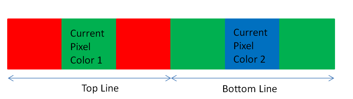
In the VisualApplets design example "BilinearBayer_RG_GB.va" the Bayer demosaicing for a bilinear line scan camera with colors red or blue followed by green in the first sensor (top) line and colors green followed by blue or red in the second (bottom) sensor line (or vice versa) is implemented. See Fig. 251 for the visualization of the sensor layout.
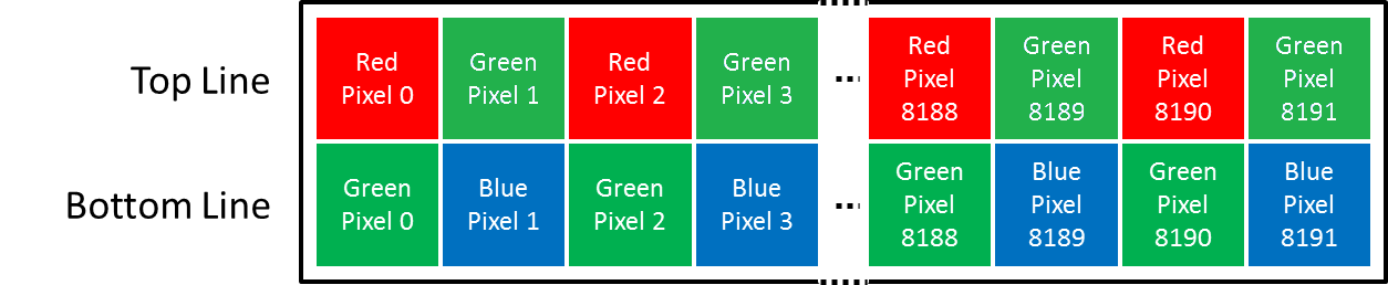
Figure 251. Sensor layout of a bilinear line scan camera with color pattern Red/BlueFollowedByGreen_GreenFollowedByBlue/Red
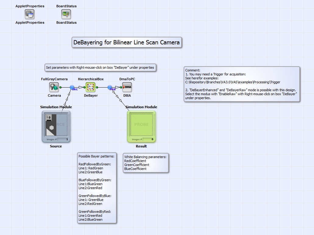
The Bayer demosaicing for this sensor layout is implemented in the applet for two camera modes: the "Bayer Raw" mode and the "Bayer Enhanced Raw" mode. In the first case the motion between two acquisitions is two sensor lines, in the second case one line. Due to this, one color component is acquired for each pixel in the "Bayer Raw" mode and two color components (red and green or green and blue) per pixel in the "Bayer Enhanced Raw" mode. You find further informations on the camera modes for example under [Bas13]. In Fig. 252 you can see the basic structure of the design "BilinearBayer_RG_GB.va".

An image acquired in "Bayer Raw" or "Bayer Enhanced Raw" mode from an bilinear line scan camera in Camera Link Full configuration (see camera interface operator FullGrayCamera) is demosaiced in the HierarchicalBox DeBayer. With "right-mouse-click" on this box you can choose the Bayer pattern under "Properties" and the white balancing coefficients for red, green and blue. The fully color interpolated rgb image is transmitted to PC via DMA. The default platform for this design is microEnable 5 marathon VCL, but it can easily be adapted to another platform. For the design you can find test images for the "Bayer Raw" mode and the "Bayer Enhanced Raw" mode under \examples\Processing\Color\Bayer\TestImagesBilinearBayer. The content of box DeBayer is shown in Fig. 253.
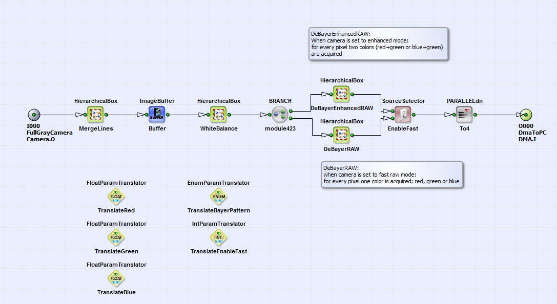
In the HierarchicalBox MergeLines the current 8 bit pixel value is merged with its neighbor in the next line to one 16 bit value. In the HierarchicalBoax WhiteBalance a white balancing of the red, green and blue components is performed. You can choose the white balancing coefficients directly with "double-mouse-click" on the operator WhiteBalanceBayer in this box or with "right-mouse-click" on the box "DeBayer" as described above. With the operator SourceSelector_EnableFast you can choose the DeBayer mode DeBayerEnhancedRAW or DeBayerRAW. In Fig. 254 you can see the content of box DeBayerEnhancedRAW.
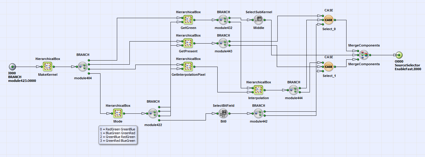
In the HierarchicalBox MakeKernel a 6x1 Kernel is created. The kernel components are the two 8 bit color components of the current pixel value ("Enhanced Raw" mode!) with its next neighbors. See for visualization of the kernel components order Fig. 255 for an example Bayer pattern of "RedFollowedByGreen_GreenFollowedByBlue".
In the box Mode you can choose the Bayer pattern in setting the operator Const_Mode to a value between 0 and 4.
See for more information on the corresponding Bayer pattern the comment box beside Const_Mode. As more comfortable alternative you
can choose the Bayer pattern of your camera with "right-mouse-click" on the box DeBayer under "Properties" on the top level of the design
as described above. In the boxes GetGreen and GetPresent the green component and the current color, which is red or blue,
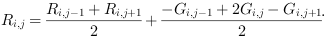
is selected for each pixel. In the box Interpolation the missing third color component red
( ) or blue
(
) or blue
( ) at pixel position
 is interpolated according to
[Bas13]:
is interpolated according to
[Bas13]:
The color components are finally merged together with the operator MergeComponents. If you choose the "Bayer Raw" mode of your camera you can choose for DeBayering of the color components box DeBayerRAW (see Fig. 253). See the content of box DeBayerRAW in Fig. 256.
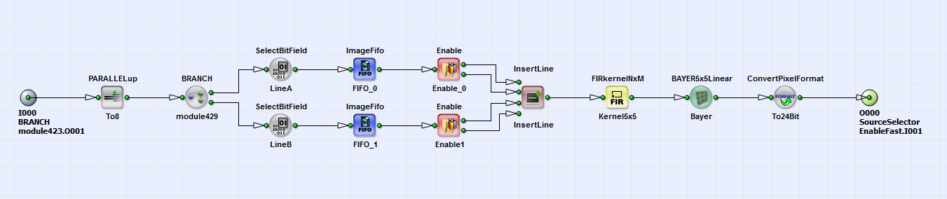
Here the DeBayering of the color components is performed with the operator BAYER5x5Linear on a 5x5 kernel around the current pixel. The color interpolated image is then transmitted via DMA to PC as shown in the basic design structure in Fig. 252.
